For specific instructions on installing Dawes Devices MBCs and other products, use the buttons below.
Multi-Boost Control System Instructions
Congratulations on your purchase! Your MBCS solenoid may be used to switch between high and low boost modes with the included 12 volt switch. Note that the solenoid has no polarity requirements, so it cannot be wired backwards. Also note that the instructions and drawings refer to a “low” and “high” boost controller. The boost limit of the “low” controller must always be lower than the “high” controller for the system to operate correctly. Also, since the system is designed for use with a ball/spring type controller, a bleed-type controller cannot be used without the addition of a checkvalve (email us if you are using another brand of controller and are unsure of the type).
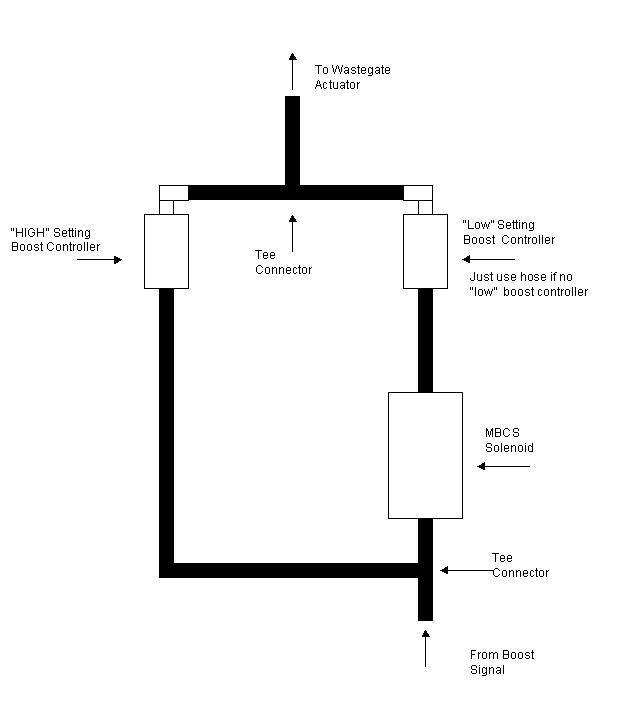
The system works by allowing boost pressure to flow through the solenoid and into the “low” boost setting boost controller, when the solenoid is energized (switch is “on”). A piece of hose may be substituted here, if you are using the wastegate actuator as the “low” setting. The solenoid has two ports. One port is for the incoming boost signal from the turbo or intake manifold. The boost supply feeds the attached “tee” fitting, with the remaining branch of the tee leading to the input side of the “high” boost level controller. Refer to Diagram A for an illustration. Variations on this design may be achieved by adding a second boost controller, or by cascading multiple solenoids for 3, 4, or more boost levels. Remember to use snug fitting vacuum hoses and ty-rap all hose connections, for safety.
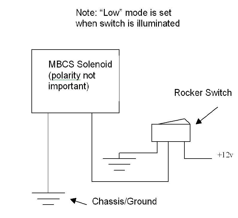
The switch is connected to 12 volts, chassis ground, and the solenoid according the Diagram B and the tag on the switch. It is a good idea to make the 12 volt connections to a “switched” supply that will shut off with the vehicle, in case the switch is left in the on position. Additionally, the supply should be fused to protect against shorts in the wiring.
Take care to mount the solenoid away from the turbo and exhaust manifold to prevent damage to its insulation. It may be mounted by using the screw holes in the base, or with wire ties.
Diagram A–Vacuum Tube Routing
Current draw of the solenoid is less than 2A
Diagram B–Wiring